Automated Bio Nutrient System
November 2023 - April 2024
Problem Definition
This project aims to research, design, and build an automated
bio nutrient system that is capable of growing herbs and small garden
plants in a small footprint with minimal user input and maintenance.
Hydroponics is a method of growing plants without soil, and instead
using a nutrient solution pumped continuously or periodically to the
roots of the plants. It is important that the plants receive
appropriate amounts of water, nutrients, oxygen, and light in
appropriate intervals to grow.
Desired State
The desired state of this system is an “Ebb and Flow” style
bio nutrient system. The system will fit in a relatively small
footprint compared to other systems on the market, allowing for it to
be used in as many spaces as possible. This system will provide the
plants with water, nutrients, and oxygen and control the dynamics and
states of each material. This system will run autonomously once set
up, requiring only a water change every two weeks and appropriate
plant care synonymous with traditional gardening. It will have a
simple user interface with only an on/off button and a status display
consisting of LEDs that indicate the state of various system
parameters such as water change status, error detections, or low water
levels.
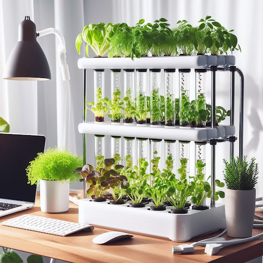
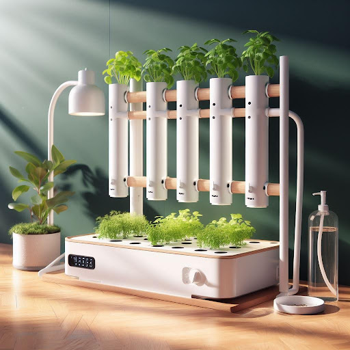
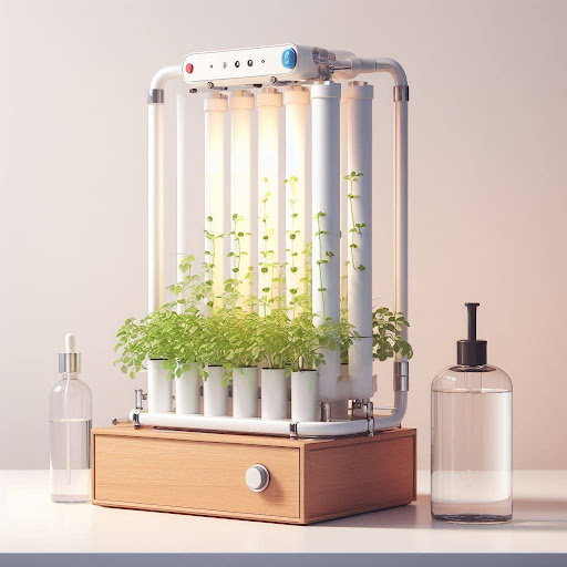
Concept Generation
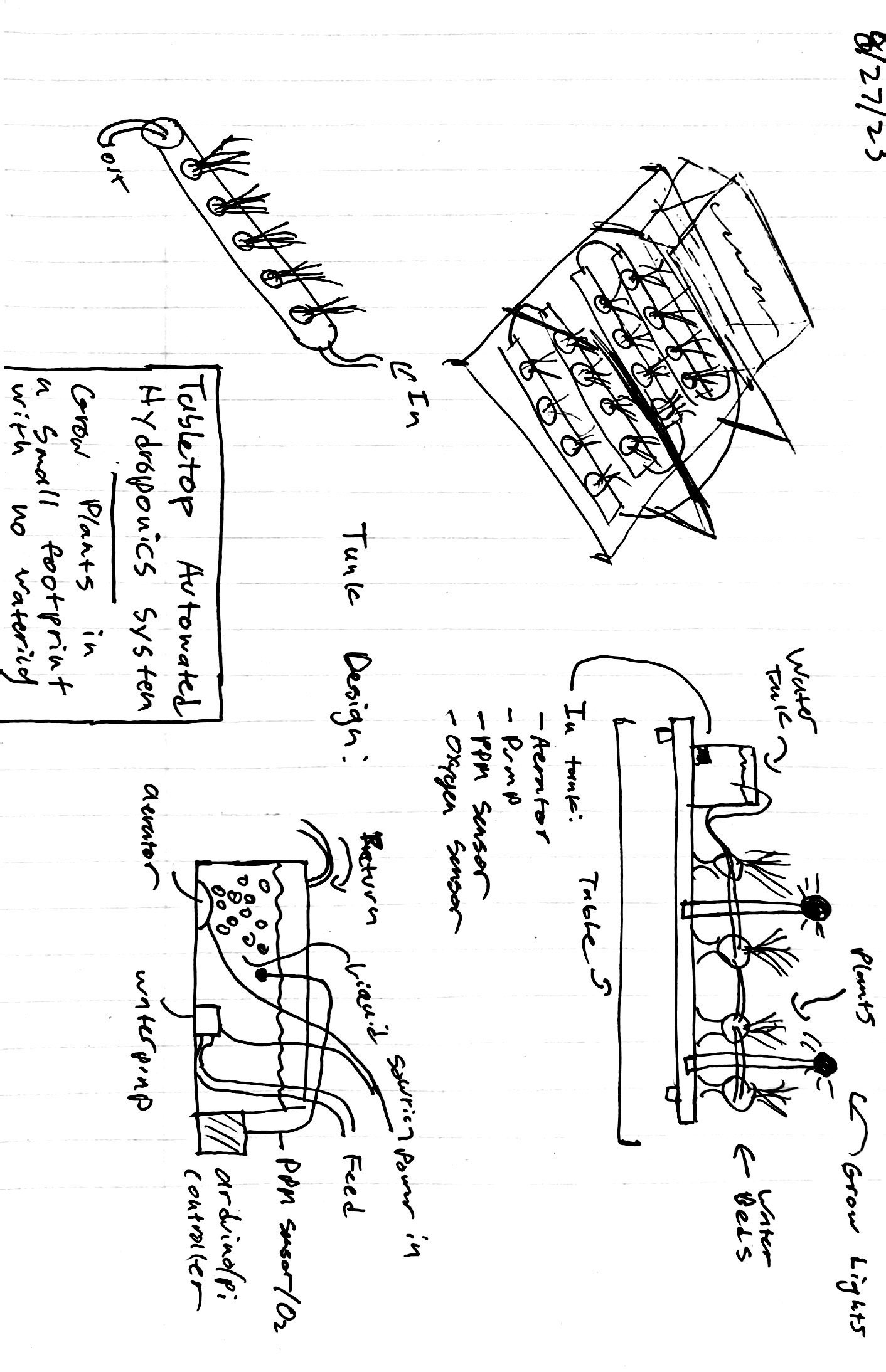
The inspiration for this project came from a previous design that
featured a tiered system capable of holding about 30 plants, and
measuring six feet high. Unfortunately, there was no space for a build
of that size available, so the concept was desired to be downscaled so
that it could be easily integrated into a small room with limited
space. Above is a high-level concept sketch and below are AI image
generations to visualize what the final system could potentially look
like and what attributes it may have.
Engineering Requirements
- The system will fit within a 28”x16”x16” area
- The system must run off of one standard 120V outlet
- The system must have a lifetime of 5+ years.
-
The system must control the flow of the liquid nutrient solution
-
The system must control the flow of oxygen to the roots of the
plants
-
The system must monitor the concentration of nutrients in the
liquid nutrient solution
-
The system must monitor the level of liquid nutrient solution in
the grow tubes
- The system must autonomously control ebb and flow cycles
-
The system must shut off inflow when the water level reaches the
maximum height
- The system must have a redundant form of inflow cutoff
-
The system must output a liquid nutrient solution change status
message
- The system must output pump status message
- The system must output flow status message
- The system must emit no more than 60 decibels
- The fluids system must be watertight without leaks
- The grow tubes must accept 2” diameter net cups
-
The net cups must be able to support 12” tall plants securely
- The net cups must be able to hold rockwool grow medium
- The net cups must allow for plant roots to pass through
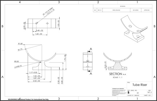
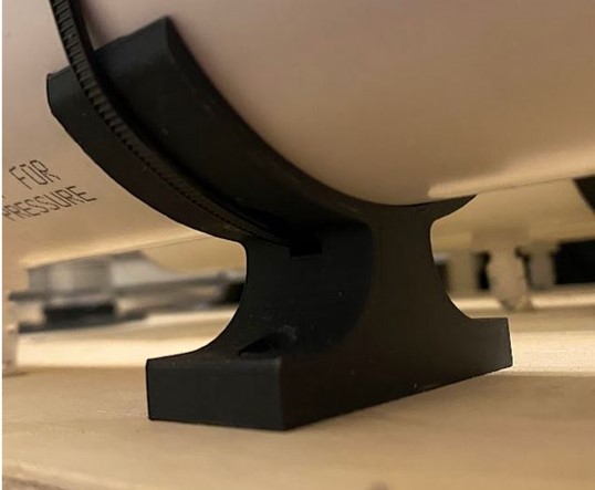
- The risers must securely support the grow tubes
- The risers must securely interface/mount to the base
-
The end caps must fit securely into the grow tubes to provide a
seal
-
The electronics system must provide power to the Arduino and
drivers
-
The electronics system must be isolated from potential fluid leaks
- The tank must hold 2 gallons of liquid nutrient solution
- The tank must be watertight and securely mounted
-
The tank must accept a tube input for removing/replenishing liquid
nutrient solution
-
The base must securely hold all components and interface with the
correctly
-
The electronics box must securely hold the Arduino/drivers/pump
-
The electronics box must separately house the pump for safety
-
The pump driver must be capable of supplying appropriate power to
pump
-
The overall system must be somewhat aesthetic and visually
appealing on a desktop
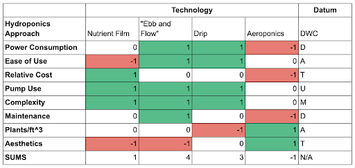
Design Selection
There are several different approaches to hydroponics. Most variations
are different in their delivery of LNS to the roots of the plants.
Some, such as deep water culture systems (DWC), continually deliver a
flow of oxygen and LNS to the roots while others, such as an “ebb and
flow” system cycle LNS to the roots and cycle exposure to air. To
determine what system would best fit the requirements for the desired
system, a selection matrix was used with a DWC system for the datum as
this was the system designed for the larger-scale bio nutrient system.
Additionally, a functional decomposition was used to help identify
what characteristics the final system will need to have.
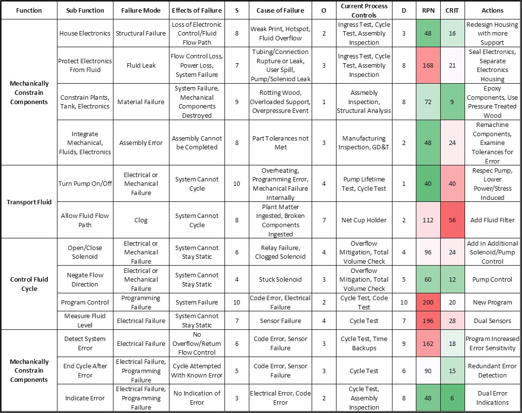
FMEA Process
Before beginning explicit design work, an FMEA analysis was performed
on the system to evaluate potential failures and causes/implications
of components and subsystems within the design. This process helps to
guide design choices and determine tradeoffs between different
components and assemblies. The RPN and CRIT values for each function
demonstrates how likely a function is to fail, and how consequential
that failure would be.
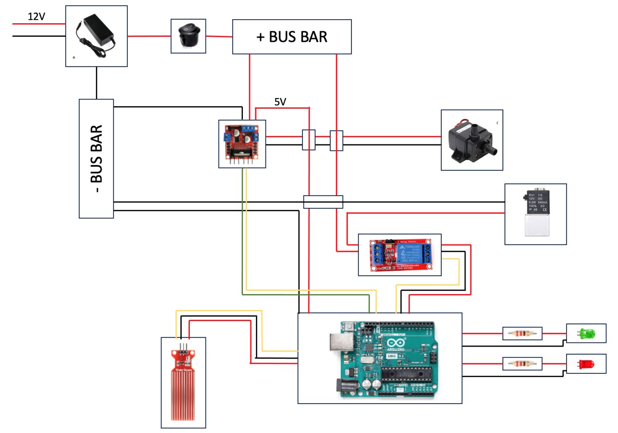
Electrical Architecture
The electrical system of the ATHS serves to power the pump and water
level sensor, as well as indicate the overall health and status of the
system. It is centered around a basic Arduino-style microcontroller
that runs off of a 12v power supply. The pump is controlled by a L298N
motor controller and the water sensor are wired directly to the
Arduino with an analog signal input to the board. There is a power
switch that does not cut off power but serves as a signal to the
Arduino to begin the system cycle. The system status indicators are
two LEDs, a green one that indicates if the power is on, and an RGB
that outputs different colors that correlate to a different system
statuses, such as low water, pump error, cycle running, etc. Each
diode requires a 220Ω resistor in line with its positive connection.
Below is a diagram of the component mapping and the wiring
configuration.
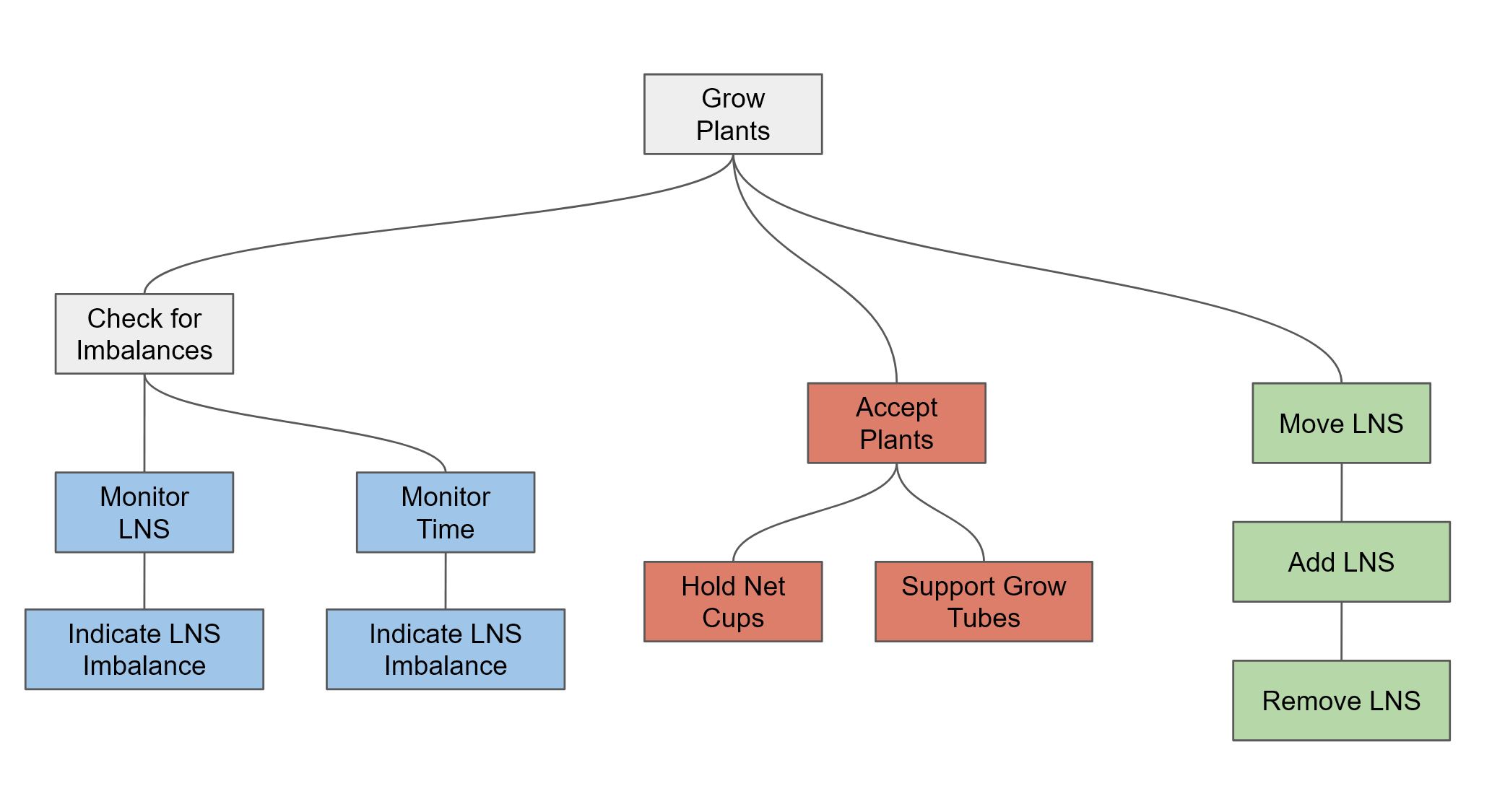
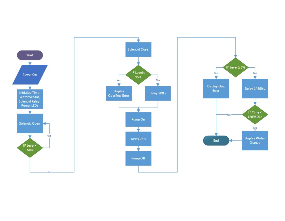
Control Logic
The control system of the device runs on a standard Arduino Uno.
First, it checks initializes power and sensor data and begins the
inflow cycle by opening the solenoid valve. Then, it monitors the
inflow of the LNS via the water sensor. Once the full value is
detected, the solenoid is closed and the plant roots soak in the LNS
for 15 minutes. Next, the outflow cycle is triggered and the pump
turns on which moves the LNS back to the reservoir. Finally, the cycle
time is checked against a control value range to determine if there
may be a clog in the lines. If there is, this is communicated to the
user via a red LED. The cycle repeats in 4 hour increments until two
weeks time is reached at which point it deactivated until the LNS is
replaced.
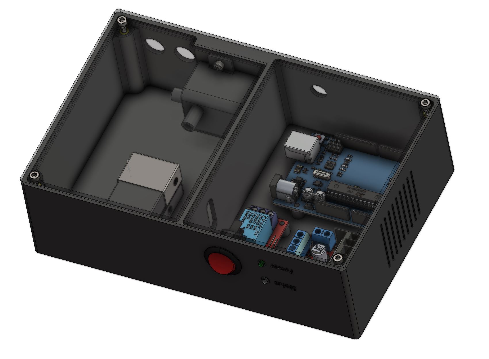
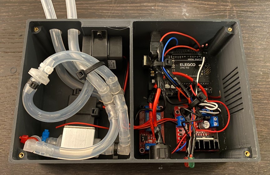
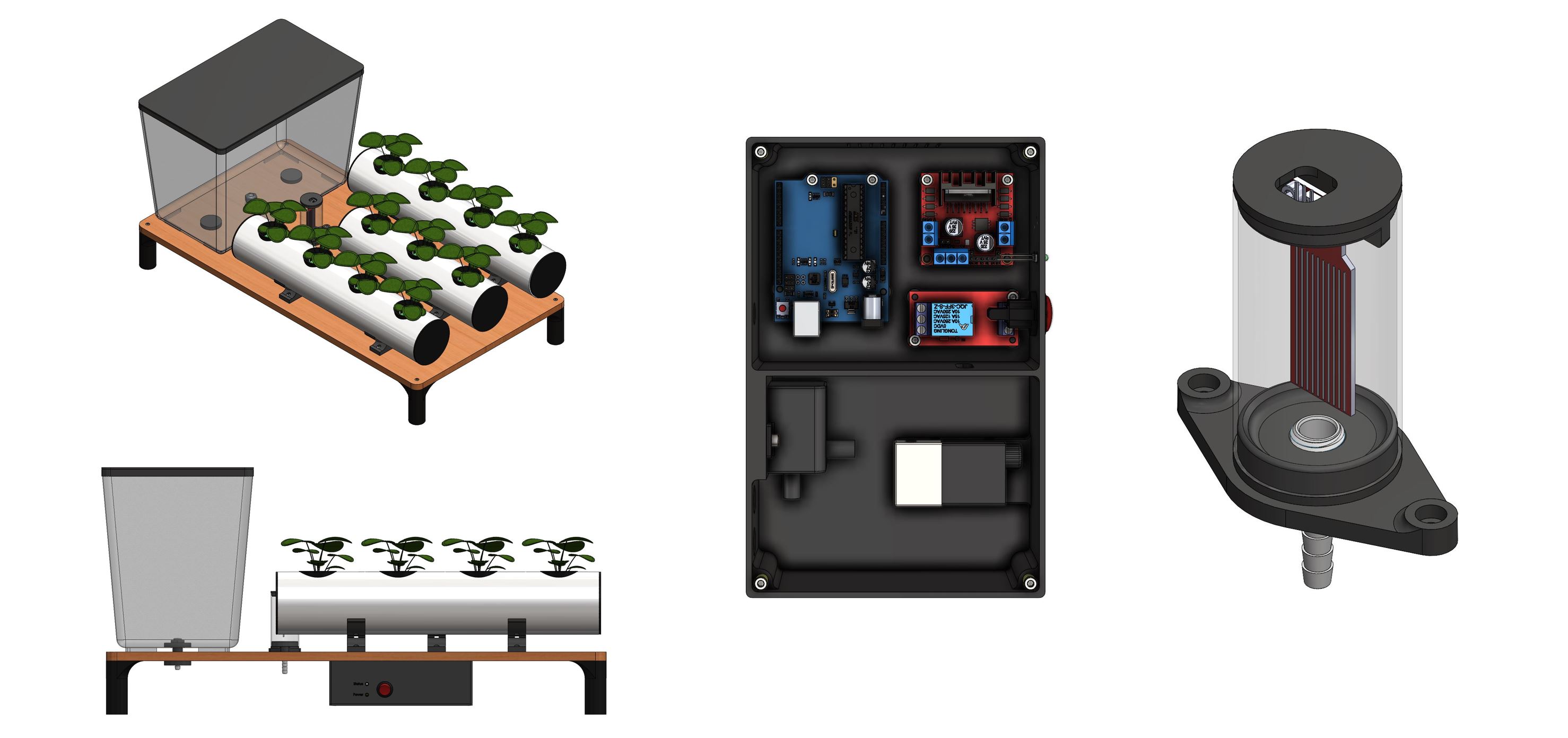
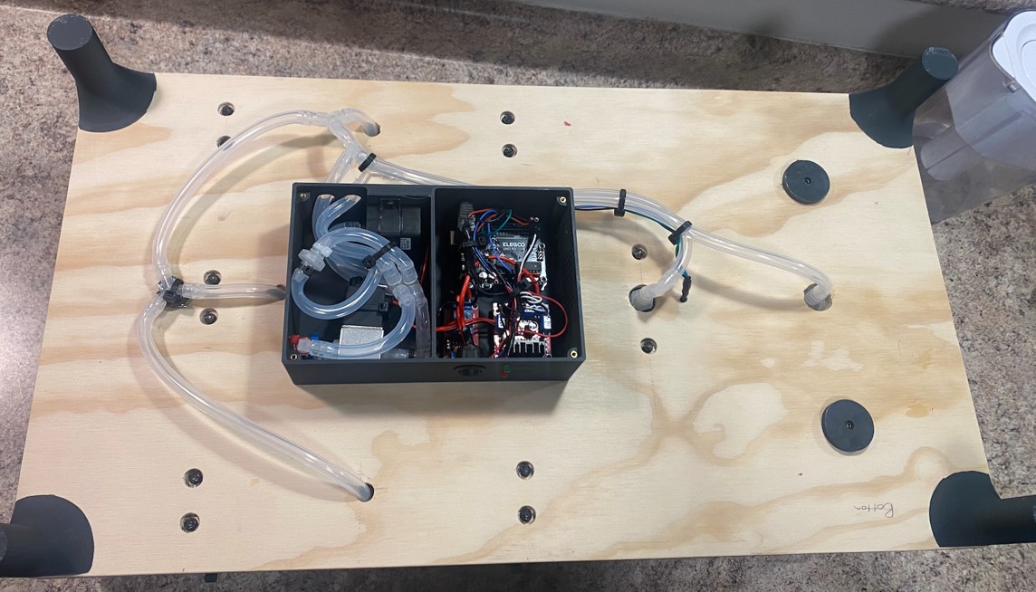
Electronics Housing
The design model began with the electronics housing as it would
control the rest of the components in the assembly. The housing was
designed to hold the Arduino, pump driver, power switch and LEDs,
solenoid and relay, and the water pump with tubing and fittings. The
structure was 3D printed and assembled with brass inserts and screws.
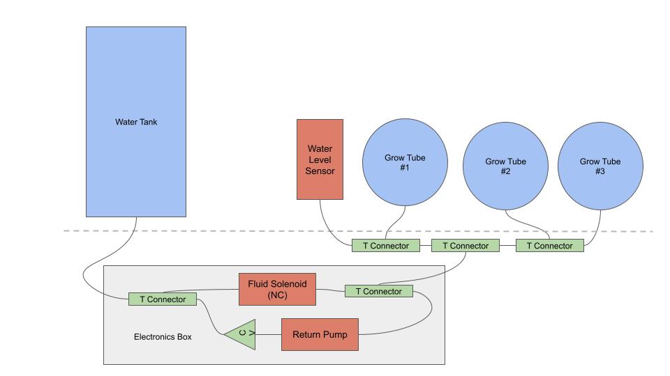
Fluid Dynamics
The fluid control system moves the LNS around the main system. On
timed intervals, the solenoid opens and allows LNS to flow
unobstructed to the grow tubes and water sensor by utilizing gravity
(and primes the pump), and the solenoid closes once the water sensor
detects the level is correct in the grow tubes. The roots soak for 15
minutes, then the pump is activated and moves the LNS back into the
reservoir. In line with the tubing is a series of check valves and
t-connectors that split the lines and prevent backflow through the
pump.
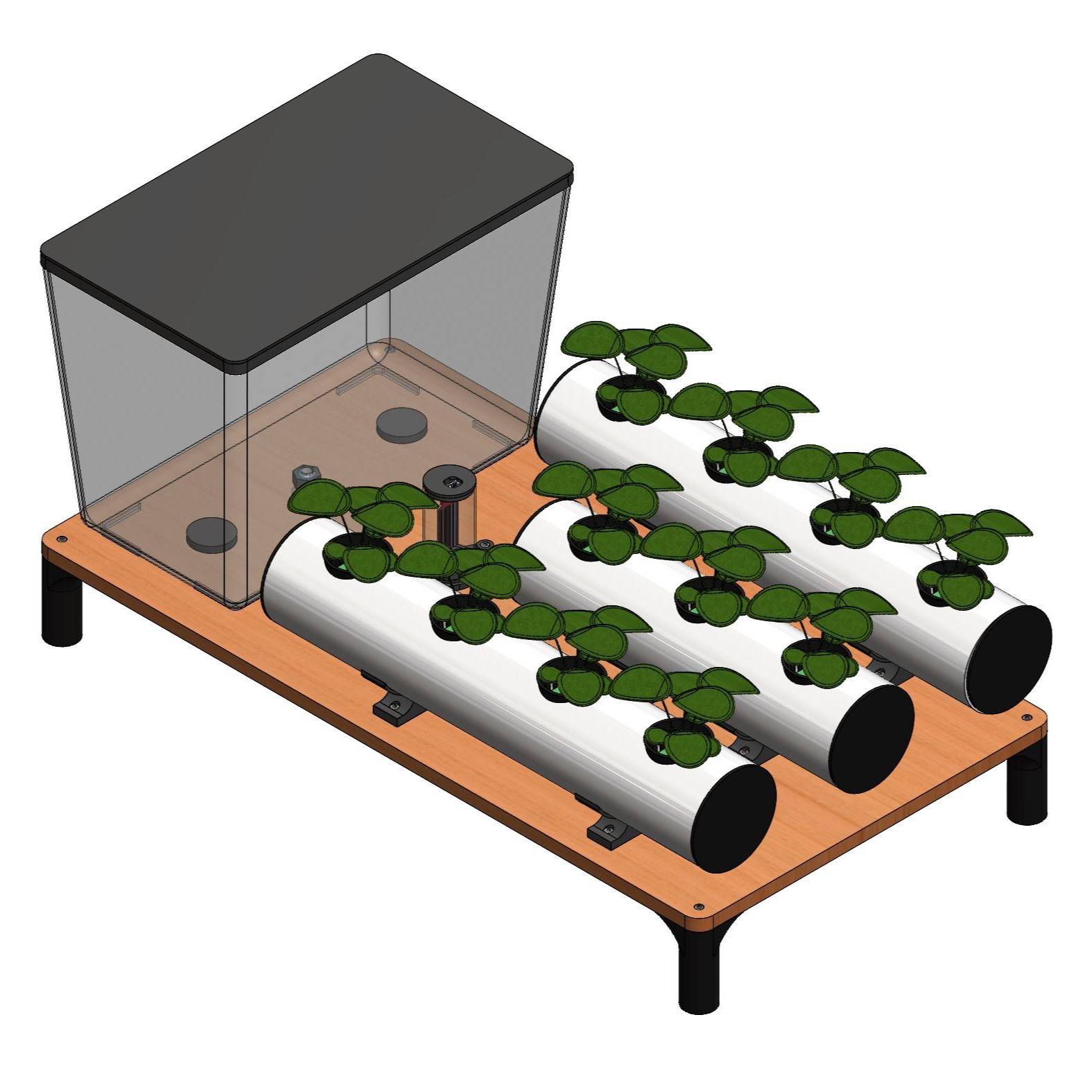
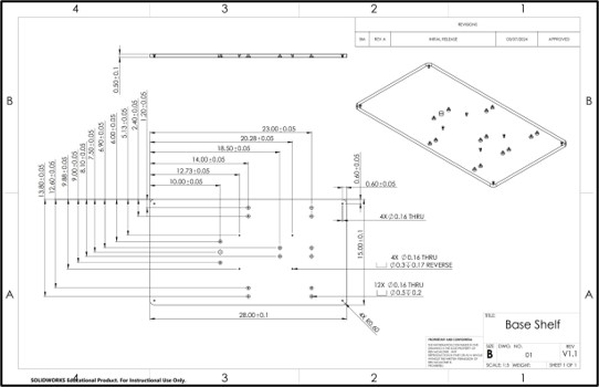
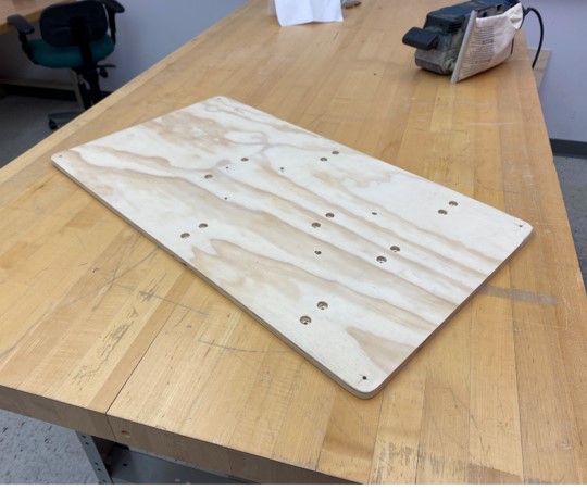
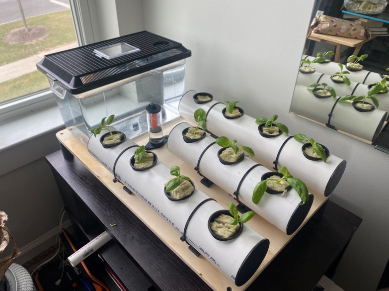
Mechanical Design
The mechanical design of the system contains all the structures and
fluid tubing, as well as fasteners. The overall design consists of a
main wooden base plate with three grow tubes that collectively hold 11
net cups and plants. The LNS reservoir is a 2.5-gallon glass fish tank
that flows into the electronics pump housing where it is distributed
to the water sensor and the grow tubes. The electronics housing is
mounted on the underside, as are the tubing and wiring.
Build
The build process involved cutting and machining the wooden base and
PCV tubes abd 3D printing the tube caps, tube risers, electronics box,
and other small components. These, along with off the shelf components
such as the reservoir and tubing were assembled into the final device.
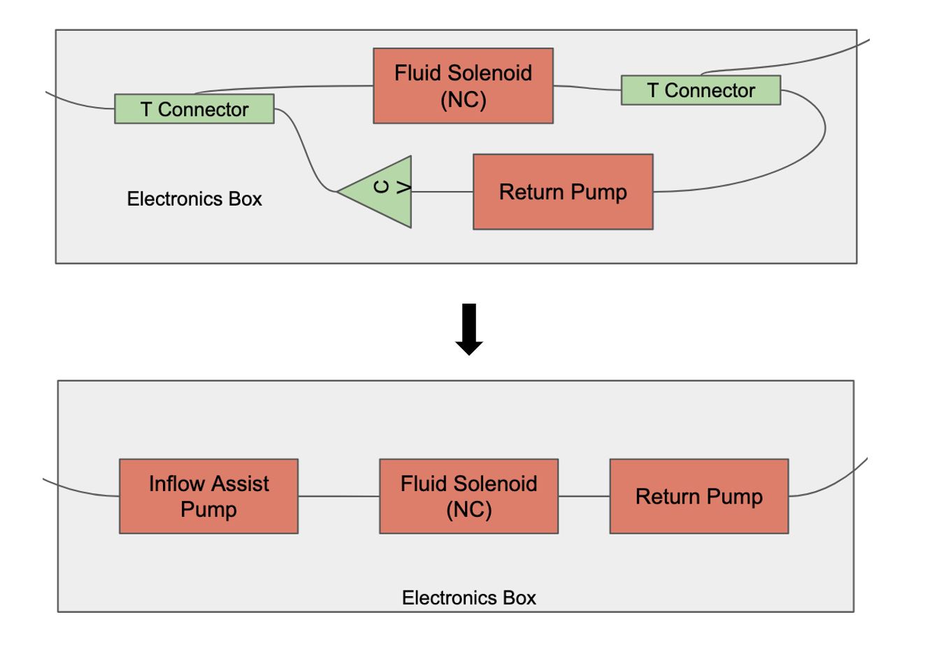
Design Fix 1: Pump Reconfiguration
After testing the overall system, it was determined that the pump
would not work in its original configuration. Due to the tube routing,
upon the inflow cycle air pockets would accumulate the pump impeller
chamber resulting in an inability for the pump to prime. To fix this,
the twin-route configuration was removed and instead two inline pumps
(with the solenoid in the middle) were added. Now there is only one
line into and out of the grow tubes, and any air pockets would be
immediately push out of the line when on of the pumps was activated.
This also decreased the inflow time and results in an overall
reliability improvement of the system.
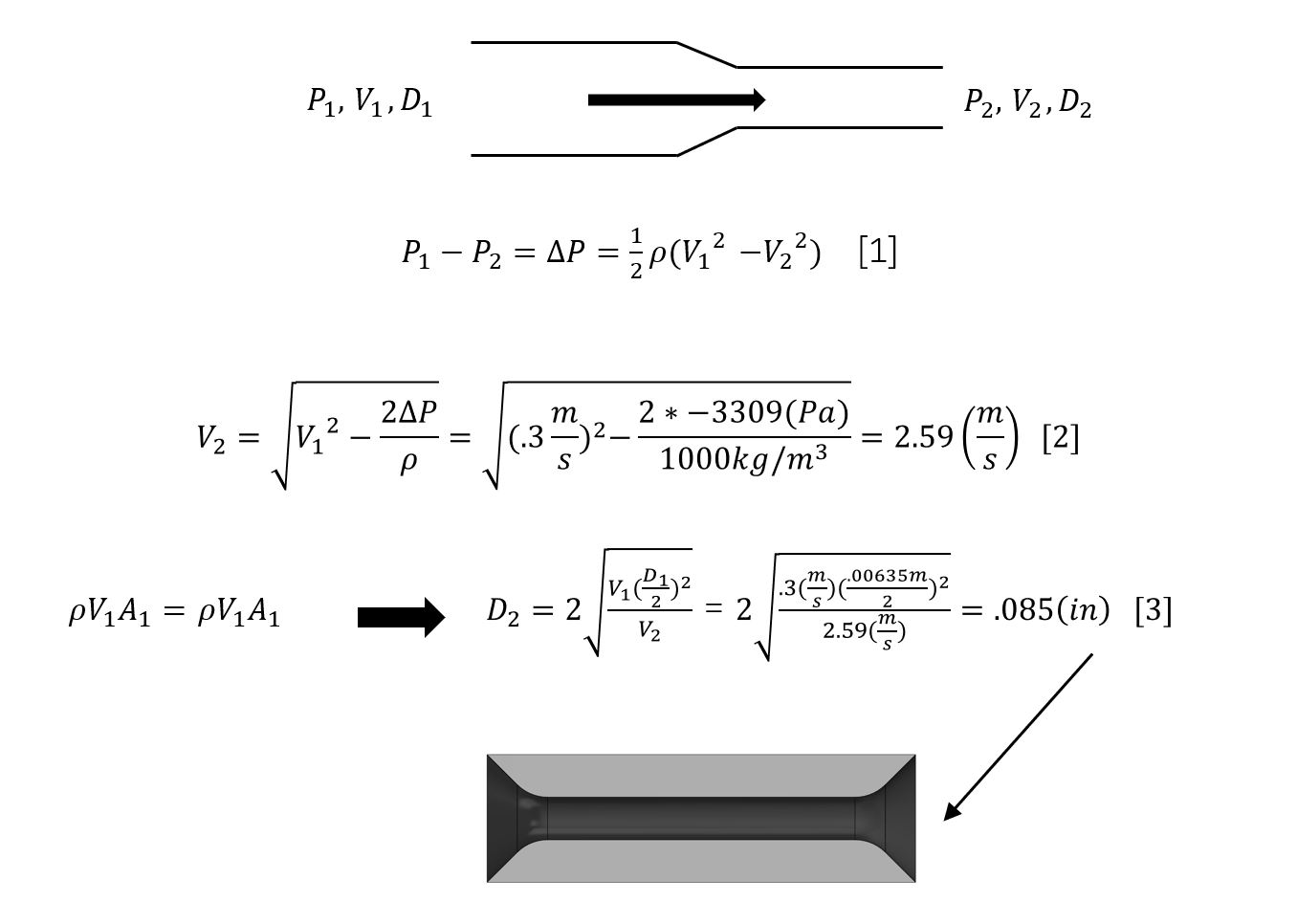
Design Fix 2: Flow Restriction Plate
During flow cycle testing, it was observed that the water sensor
chamber filled much faster than the grow tubes. This was due to the
additional tubing and connections in line between the pump and grow
tubes when compared against the line between the water sensor and
pump. To fix this, a flow restriction plate was designed utilizing
Bernoulli's equation to solve for the required reduction in the
diameter of the tube that would increase upstream pressure in the line
and result in a lower volumetric flow rate into the water sensor
chamber. After 3D printing and installing the flow restriction plate,
the tubes filled equally and an accurate infill cycle level could be
measured.
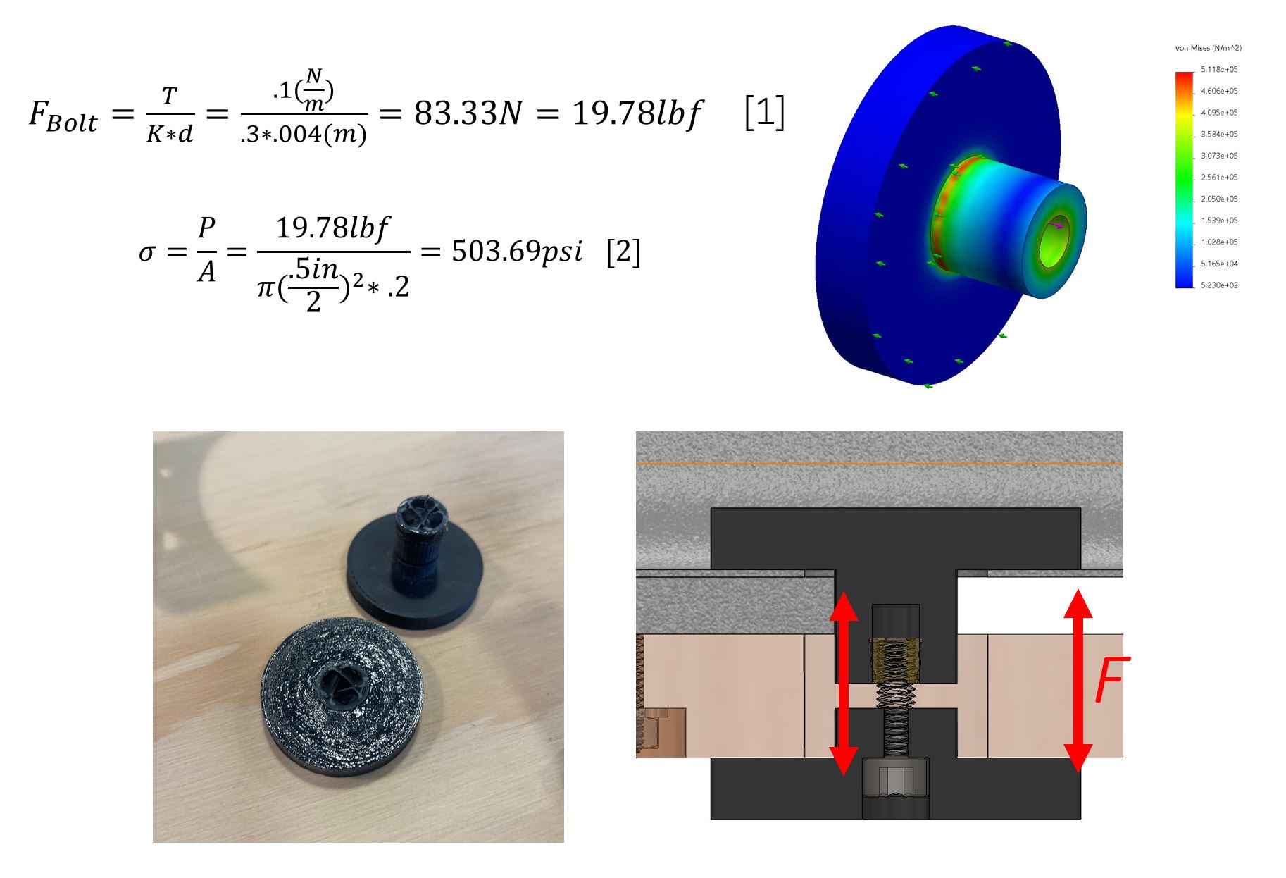
Design Fix 3: Tank Support Redesign
When building the tank structure, the 3D printed tank bolts snapped,
resulting in fluid leaking out of the tank and an unconstrained
reservoir structure. To assess the cause of the failure, a strain
analysis was performed on the bolt which determined that the applied
load's resulting stress was within the material's tensile yield limit.
However, it was possible that the addition of an epoxy resin weakened
the material, causing the failure. To fix this, a higher infill was
used in the print programming which meant the resulting bolt had a
greater cross sectional area and thus experienced lower stress. The
new bolts were also annealed in an over at 180F for one hour to allow
the amorphous crystal structure of the plastic material to settle. As
a result, the new bolts carried the load easily.
Use Case
This design is meant to be used by individuals who want to easily and
sustainably grow plants, but do not have a garden or enough space for
a full-size bio nutrient system. It is meant to be compact and simple
while retaining organic aesthetics so that it can be used in small
spaces.
Current State
As of 4/1/2024, the design is complete and operational. Currently,
optimization of the flow cycle timing is being developed and measured
for different types of plants. Version two is in the conceptual phase,
with plans to add artificial lighting and PH/PPM sensors to the
system.
Next Steps
Once the model is built, I will run it and evaluate it to make sure
all engineering requirements are met, and build a second version. One
of them will be used by another individual for user experience
testing, and I will work with their feedback to continue the design
improvements.
© 2024 Benjamin McAlonie. All rights reserved.